by chris
Share
Having started to get to grips with our new (old) boat, the time has come to deal with most of the switches not working and many of the lights too.
This is a story of what seems a simple job, escalating but with some sound advice from my work colleagues (I work for a marine electronics company), I was able to break the job down whilst still keeping the boat in commission. Here’s a breakdown of what I wanted or needed to do.
There were two main electrical tasks I wanted to deal with. Firstly, I wanted all the switches to work and secondly I wanted to have a separate engine start and domestic battery and be able to monitor them. I bribed a friend and marine electronics engineer to come to the boat, assess what needed doing and come up with a plan of action along with giving me the courage to dive in and cut holes in things, cut cables and so on.
The appraisal
- The boat had 2 x 110Ah AGM batteries for domestics and starting using a 1 / OFF / 2 / BOTH switch to set which battery was being used. Essentially, both batteries were being used as starter and domestic at the same time.
- POSITIVE earth system.
- Most of the wiring was from 1968 using non-tinned copper wire, mostly buried in foam between 2 layers of GRP that make up the headlining.
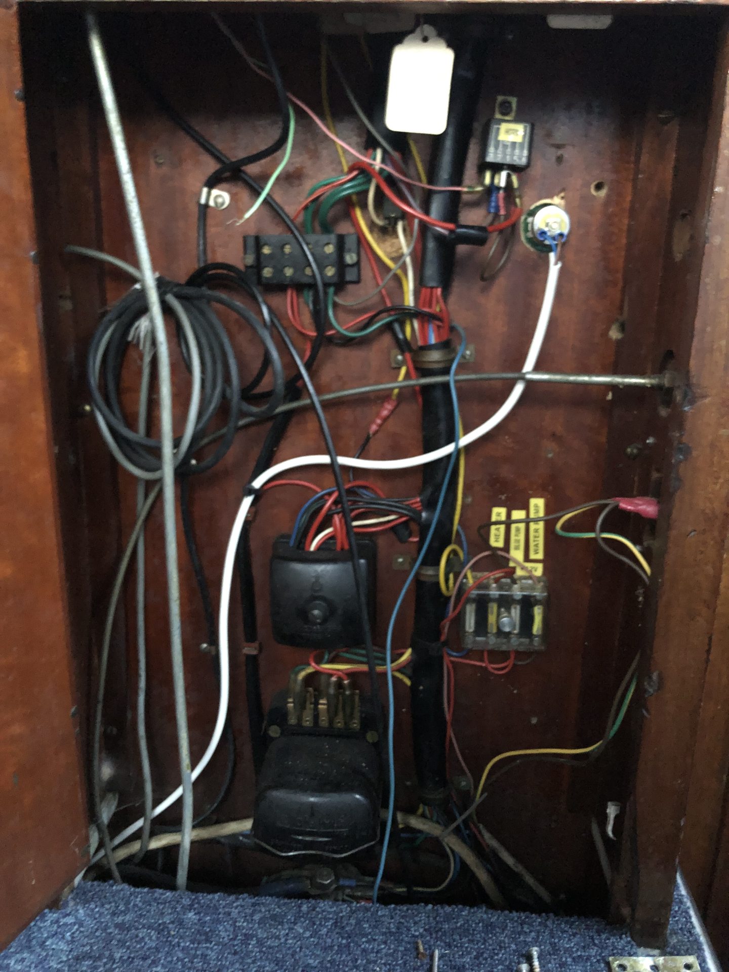
- The electrical compartment was a mess with many cables squeezed into connectors that simply couldn’t contain them.
- Several additional fuse boxes were piggy-backed off others with all manner if jumper cables being used or t’eed off from other parts of the boat rather than running new ones.
- Temperature sender and gauge had failed
- Warning lights were intermittent
- Ignition switch had a very flimsy key that felt like it would snap without notice
- 1 / OFF / 2 / BOTH switch was completely inappropriate for the job (as it is on most boats !)
- Original dynamo
- Much other wiring was using poor grade cable.
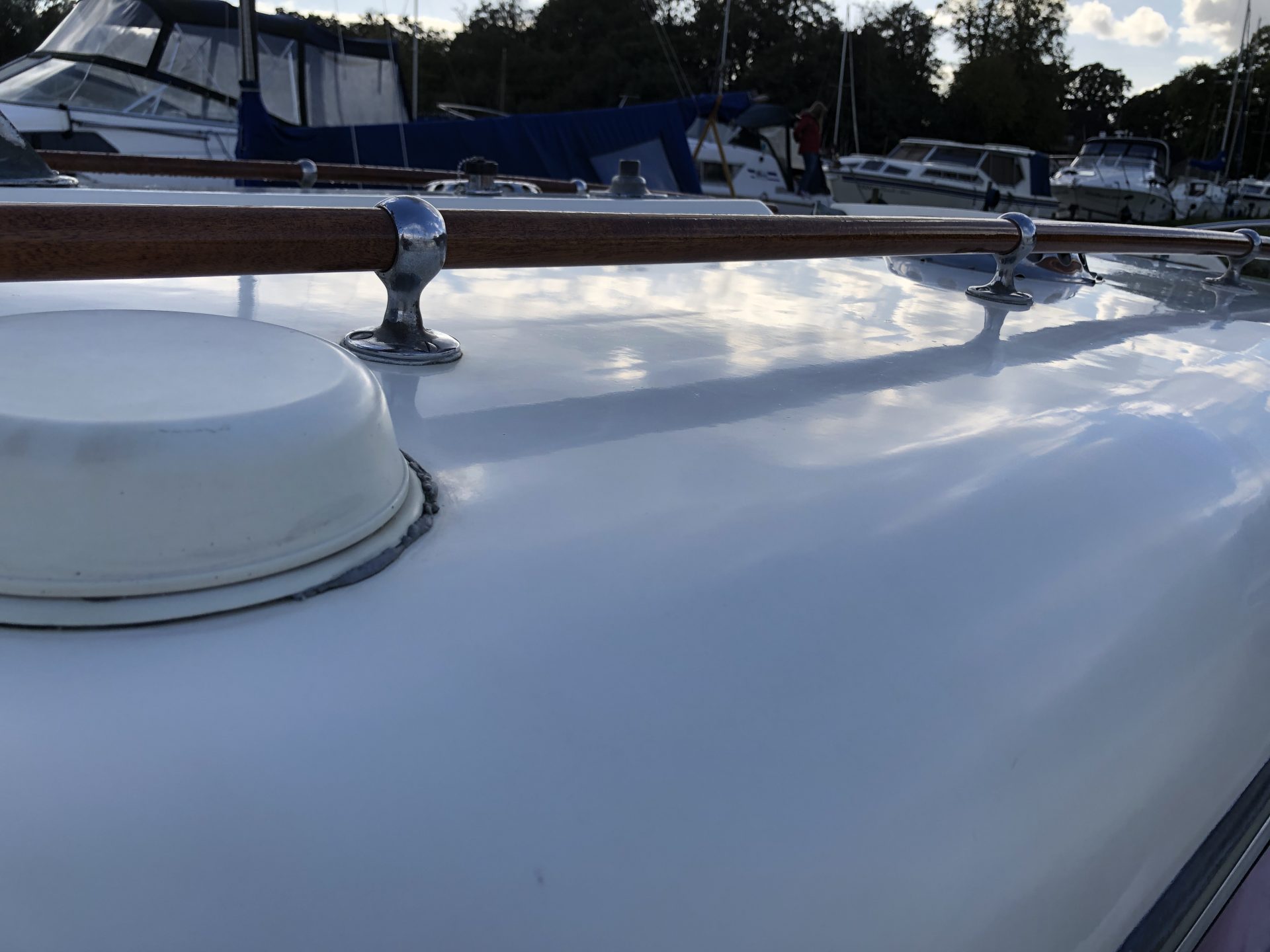
- All the chrome deck plugs had leaked and corroded beyond reliable repair.
There was clearly much to do ! The key was prioritising rather that tearing everything out in one go and being clueless on how to put it back together.
The following sequence of events may not have been optimal, but it did keep the boat mostly operational without becoming a project as such.
Negative Earth
Many cars of the 60’s era were set up as a positive earth to prevent interference to car radios. There may have been plenty of other reasons too but modern 12v electrics generally require a negative earth. As I wanted to eliminate all manner of complications and brain-freeze down the line, I needed to change the electrics on White Lady to a negative earth. A bit of research and this wasn’t too difficult. I found this article essential “How to convert your car from positive earth to negative earth”
Battery Switch

I now had two independent batteries to work from with the engine start battery being connected to the charging circuits (I already had a mains battery charger in place). A voltage sensing relay (VSR) was added between the engine start and domestic battery so that once the engine start battery was fully charged, it would then ‘spill’ charge into the domestic battery. This means that at even if my domestic battery goes flat, I’ll still be able to start the engine.
A VSR beats a charge selection switch hands down unless you like things really basic and can remember which battery needs charge. What theoretically would be better still is to use a DC to DC charger. This is basically a battery charger with all it’s nice charging profiles that uses another battery as it’s power source. It’s a nice thing to have, but for £35, a VSR works fine for me.
Electrical Compartment
This is where Tom’s (my electronics engineer buddy’s) wisdom and experience made the work do-able in bite sized chunks.
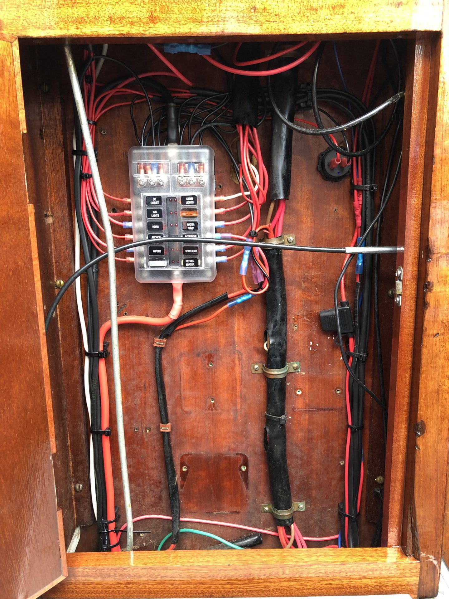
Broadly speaking, I would tidy up the electrical box by removing various bodges and fuse boxes and replace them with a clean and tidy ‘domestics’ fuse box with blade fuses, blown fuse indicators and an integral negative bus bar.
The idea was to migrate individual circuits one by one, as time permitted, to this ‘domestic’ fuse box. Although I wouldn’t have a truly isolated domestic battery until I’d migrated the last circuit to it, the boat could remain in commission.
You can see the before and after picture to see the new fuse box and new supply cabling coming from the domestic battery (via the dual battery isolation switch I mentioned earlier)
In the ‘after’ picture you can see that most of the circuits are in place but how they got there is for later down the page. You’ll also see that the dynamo voltage regulator has gone having fitted an alternator. This is where I was about to become slightly diverted, replacing a very low output dynamo for an alternator which was now relatively straightforward to do given that I was now on a negative earth.
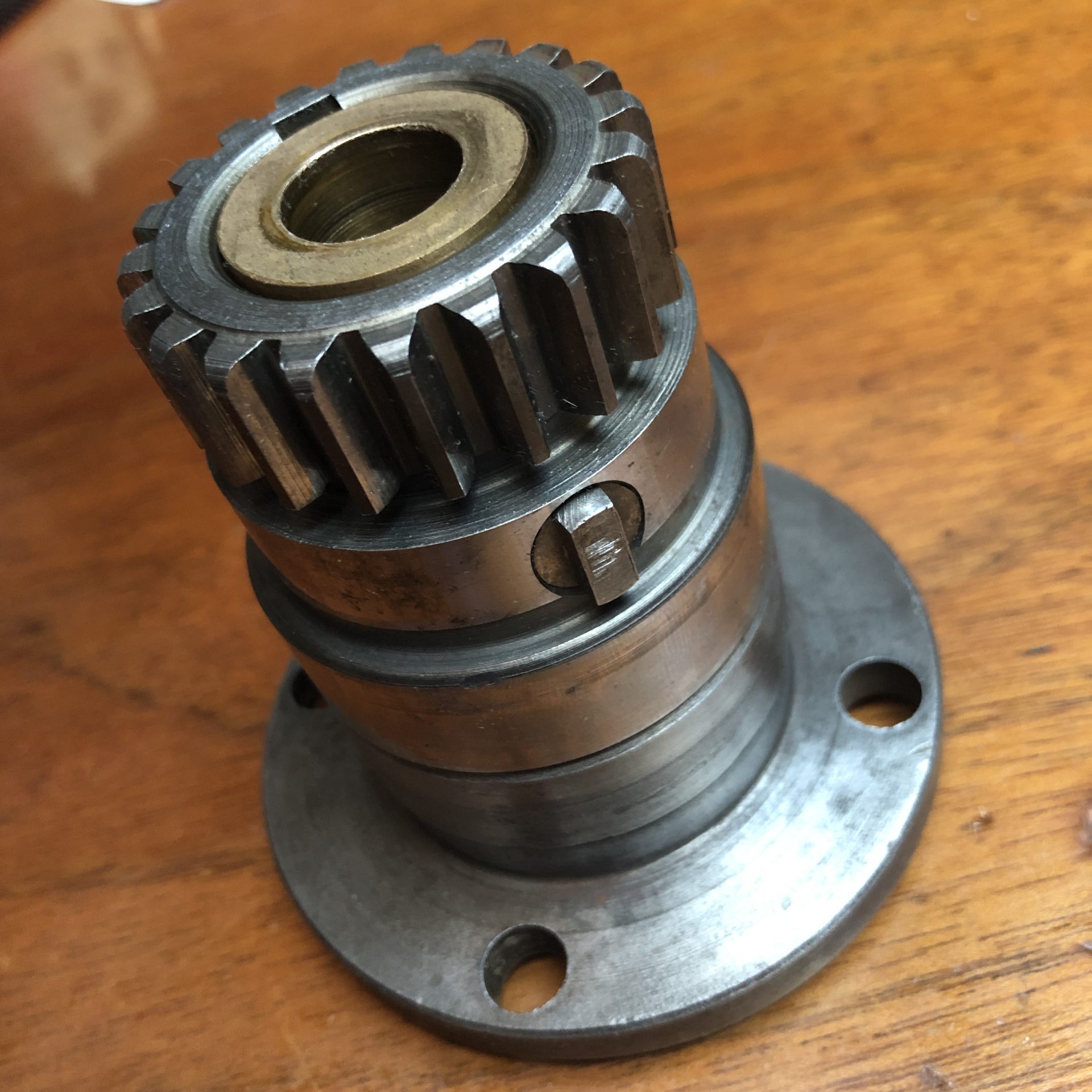
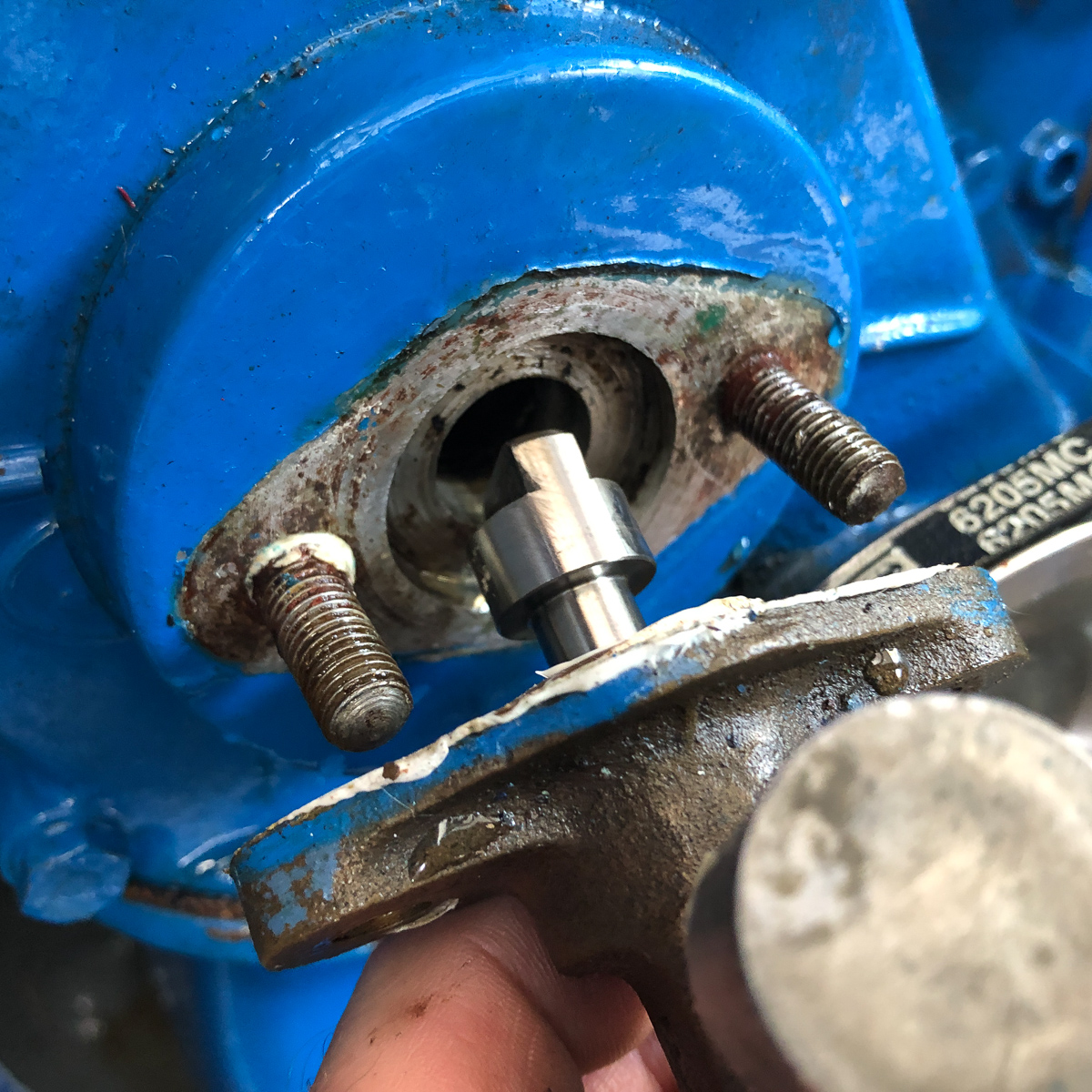
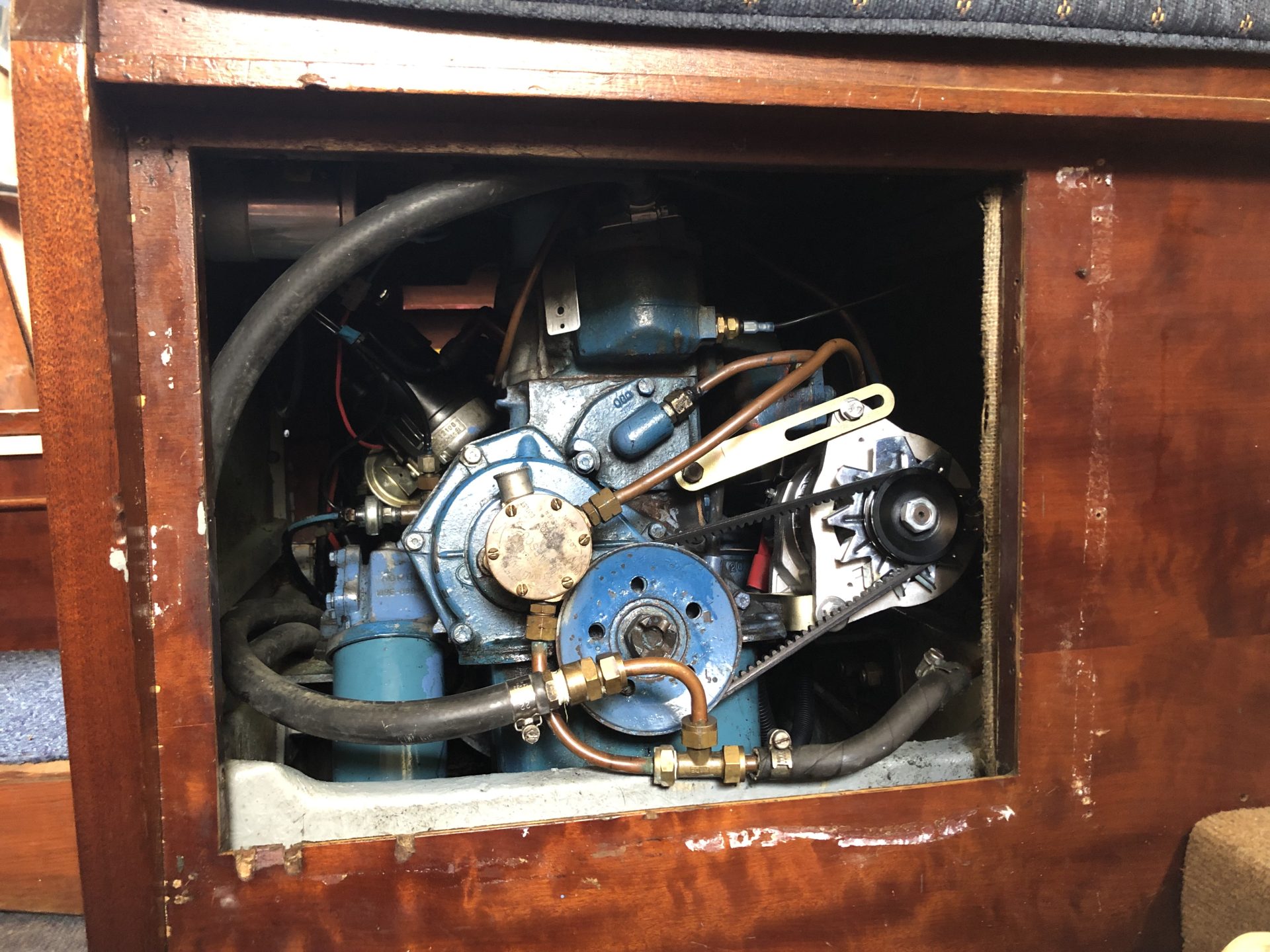
Alternator
Converting to an alternator was a no-brainer given they’re not that expensive unless you go for one of those replica type ones that look identical to a dynamo and fit in the same way.
For me, originality in an engine compartment is a bit over the top however it was a minor challenge figuring out how to get one to fit. The engine main block casting has two mounting bolts to which I had to fit a new alternator bracket which I found from a supplier on eBay. It’s a quite simple affair, but if you don’t know what you’re looking for, it’s a head scratcher.
Once I had a bracket, a Lucas pattern alternator (18ACR) and a slightly longer toothed V-Belt, I was getting close. I went for a 55Amp model but had to make up a ‘double’ cable to split the capacity across two wires. The back of the alternator has two spade terminals which you can use together. I bought the appropriate 18ACR plastic plug connector to make up this ‘loom’ although one could probably just use the appropriate spade terminals.
The alternator was wired to the starter battery and I could joyfully remove the ugly voltage regulator from my electrical box.

The description for these brackets if you’re doing a search is ‘Ford xflow/ crossflow Alternator bracket set Zinc Plated Cortina, Escort, Fiesta’
Rewiring
Now that I had a fuse box to take all my wiring to, it was a matter of establishing which cables were good, about to go or gone.
It turned out that pretty much everything needed replacing. The biggest issue was that most of the cables run through the foam sandwich of the headlining and that the cables were the originals from 1968 and simply standard copper. There were no conduits and as the deck connections were the pretty, but useless chrome type ones. Water ingress had wicked in to the cable a destroyed them. I knew that there would be at best a 50:50 chance of pulling new cables through with the old ones but it was worth a try as failure would have meant cutting access panels into the thin GRP headling from underneath which would have looked awful.
Having consulted a rather useful facebook group, I established the route the cables were likely to take and so starting with the main saloon cabin lights I removed the drinks cupboard from the main bulkhead which revealed the access point of the cables into the headlining. It was definitely a case of one out, one in as the cables were on the cusp of breaking. I used copious amounts of washing up liquid as a cable lubricant and came up with a good strong method of joining new and old cables together to pull through without increasing the cable diameter whilst using a minimal amount of electrical tape. I carefully used pliers to get things moving. It was probably more luck than judgement that I was able to pull all new cables through without them snapping.
I replaced all the light fittings with LED’s or LED bulbs, so was able to use tinned 1mm cable for the saloon lights.
The deck electrics were a further challenge as the Freeman spot light cable was pretty under-specified. I replaced this with 2mm tin tinned cable and frankly, it was a hell of a challenge to pull through ! Long nosed pliers were essential for this operation and you definitely need to think carefully which cables you can pull out or need to keep as pull-throughs. This is heart-in-mouth stuff ! Once I’d done the spotlight, I went for the anchor light and finally the socket for the horn. I don’t have a horn yet but replaced the cable to the socket with some 2mm cable as horns can pull quite a bit of power.
The only original wire I kept that ran through the headlining was the one to the wipers which seemed OK, probably because there’s little chance of water ingress having the socket under the canopy.
Elsewhere on the boat, much of the retrofitted cabling was using domestic 3-core cable, often not even using the 3 cores. I removed all of this and replaced with appropriate single and twin tinned cable depending on load. I used 1mm for things like LED lights such as one going to the heads which required me to pry the thin mahogany-faced ply back inside the heads compartment (It’s tacked into place with panel pins) and route the cable in the cavity rather than tack the cable to the outside of the bulkhead. It is a pet hate of mine to see cable attached to the outside of things with p-clips when a bit of thought and effort could hide them.
I replaced the navigation light bulbs with LED’s too.
Finally on the wiring side of things I replaced any cables which had unnecessary joins and got rid of any bodges, such as wire twisted together and covered with electrical tape. I also got rid of as many connections made with ‘chock-blocks’ as possible, replacing with new cable runs or making up proper terminals. I also made sure that all cables were supported properly with cable saddles using cable ties in case anything needed removing in future.
Switch Panel
I have a separate article on my switch panel but essentially, all the domestic circuits such as lights, heater, wipers, water pump and so on needed to be connected to a switch panel. The old panel simply didn’t have enough switches and couldn’t accommodate the displays I wanted. The answer was to make up a custom one which I’ve pictured. It would have been possible to make up a panel with circuit breakers, thus being able to dispense with a fuse box but it seemed more logical to split the fused from the panel given the space I had to work with. The panel gave me the option to replace the amp meter with a more useful battery monitor (Victron BMV 712 Smart Battery Monitor) which would give me lots of details on my domestic battery and basic information on my starter battery. It also has a great App on my phone to get even more in-depth information for when using a fridge etc.
I did decide to move my bilge pump switch onto the main panel rather than have it on the side of the electrical box although this is the only ancillary item connected to my engine start battery BEFORE the battery isolator with it’s own inline fuse. You want to be able to leave your bilge pump on auto regardless of the master switch being off.
I designed the layout of the panel in Adobe Illustrator and a local signmaker cut and engraved the panel from black anodised 6mm aluminium.

Switch panel in use